|
EXPERT
TRACKING AND MAINTENANCE SYSTEM
|
IMPLEMENTATION
This chapter will discuss
the design and implementation of the prototype system, namely Expert Tracking
and Maintenance System. It will give an overview of the architecture of
the web application. Later, this chapter will describe the prototype system
architecture and finally samples of the modeling extension for the web-based
graphical user interface design of the prototype system developed.
5.1 Architecture
Of The Web Application
According to Conallen
(1999) the architecture for a web site is rather straightforward. It contains
three principal components that consist of a web server, a network connection
and one or more client browsers. The web server distributes pages of formatted
information to clients that request it. The request is made over a network
connection and uses the HTTP protocol. Figure 5.1 shows the architecture of web
application. Some web sites require clients to logon, and some allow anonymous
access.
The information made available by a
web site is typically stored, already formatted, in files. Clients request
files by name, and when necessary, provide specific path information with the
request. These files are termed pages, and represent the content of a web site.
In some situations the content of a
page is not necessarily stored inside the file. It can be assembled at runtime
from information stored in a database (or other information repository) and
formatting instructions in a file. Alternatively, it can come from the output
of a load-able module (CGI or ISAPI). The web server uses a page filter to
interpret and execute the scripts in the page. Web sites employing this
strategy are called dynamic sites.
Figure 5.1: Architecture of Web
Application
Dynamic web sites offer certain
advantages to web site designers. They make it easy to keep the content fresh
and synchronized with data in a database. The overall look and feel of the web
site is defined by a set of pages that contain code executed by the web server
during a request for this page. In this context the file can either be a plain
text file with scripts interpreted by the web server, or a compiled binary file
that is executed by the web server.
A user interacts with a web site via
a browser. A browser is an application that runs on a client machine, which
connects to a server on a network and requests a page of information. Once the
page request has been fulfilled the connection terminates. The browser knows
how to communicate (via HTTP) to a web server, and how to render formatted
information returned by the web server. Most pages of information contain links
to other pages (possibly on other servers), which the browser user may easily
request. Users navigate the web by clicking on links and requesting pages from
web servers.
5.2 The
Prototype System Architecture
The
ETMS model proposed in this study can be implemented on several other
platforms. However for the purpose of this study, the prototype was developed
using the relational database in the web environment.
This study chooses Apache as the web server. Apache web
server is one of the two-web servers that dominate the market. The other is
Microsoft’s Internet Information Server (IIS).
Apache server is an open source, anyone with
the skill can write code that extends the functionality of Apache (Greenspan
& Bulger, 2000).
For the middleware, this study chooses PHP. PHP will most
often run as an Apache extension, known as the Apache module. PHP belongs to a class of languages known as
middleware. These languages work closely with the web server to interpret the
requests made from the world wide web, process these
requests, interacts with other programs on the server to fulfill the request,
and then indicate to the web server exactly what to serve to the client’s
browser. PHP is a cross-platform and it will run on Windows 2000/NT and Unix and with both IIS and Apache. PHP also works on
Netscape, Roxen and other wide variety of systems.
For the database, MySQL is chosen because it is free. MySQL will be extremely
fast for small- to-medium-sized databases.
There are four types of actors that
will use the system. The actors are the User, Managerial staff, Technical staff
and Clerical staff. The system architecture contains four main subsystems and
one relational database. The four main subsystems are the User management
subsystem, Equipment Tracking subsystem, and Equipment Maintenance Subsystem
and Equipment Assigning subsystem. The relational database, which is used to
store the information, is MySQL. The subsystems will interact with the
relational database when storing or retrieving information. The actors will
also interact with the systems and its architecture.
5.3 Modeling
Extension For The Web-Based Graphical User Interface
Design
According
to Connallen (1999), the latest generation of web
applications is getting complex. Therefore it is important to have modeling to
help manage the complexity. Connallen (2000) stated that the UML has been widely
accepted as the standard modeling language for software systems, and is the
best option for modeling web application designs. The Web Application Extension
(WAE) extends the UML notation with semantics and constraints enabling
developers to model web-specific architectural elements using the Rational
Unified Process or an alternative methodology. Using UML allows developers to
model their web applications as a part of the complete system and the business
logic that must be reflected in the application.
UML has defined a mechanism to allow
certain domains to extend the semantics of specific model elements. The
extension mechanism allows the inclusion of new attributes, different semantics
and additional constraints. When collected together as Tagged Values,
Stereotypes and Constraints they form an Extension to UML. Part of the
extension mechanism of UML is the ability to assign different icons to
stereotyped classes (Connallen, March 1999).
A list of prototype icons for the most common class
stereotypes and the icon used in this implementation is shown in figure 5.2
below:
|
Class Stereotype |
Common Icon |
Icon used |
|
Client page |
|
|
|
Server page |
|
|
|
Form |
|
|
|
Target |
|
|
|
Frameset |
|
|
Figure 5.2: Prototype icons for the
class stereotypes.
5.4
Modeling Extension For The Expert Tracking and Maintenance System
The
modeling extension used in the Expert Tracking and Maintenance System are shown
below.
5.4.1 Web Graphical User Interface for Main
Menu
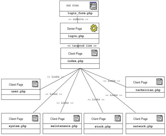
Figure 5.3 The Expert Tracking and
Maintenance System’s Main Menu.
5.4.2 Web Graphical User Interface for user
entry
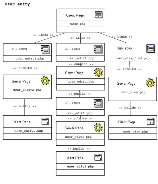
Figure 5.4:
web GUI for User entry.
5.4.3 Web Graphical User Interface for view
user
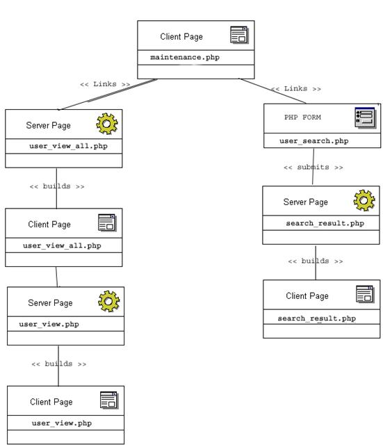
Figure 5.5: web GUI for View User.
5.4.4 Web Graphical User Interface for user
request entry
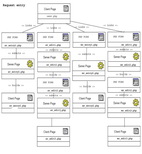
Figure 5.6: web GUI for User request
entry.
5.4.5 Web Graphical User Interface for
Maintenance
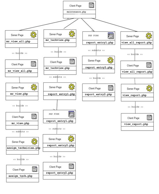
Figure 5.7: web GUI for Maintenance.
5.4.6 Web Graphical User Interface for
Assigning the System

Figure 5.7: web GUI for assigning the
system.
5.4.7 Web Graphical User Interface for
Stock
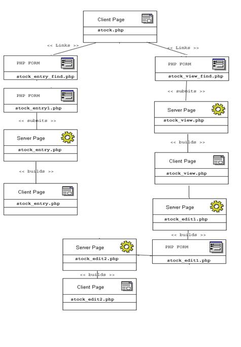
Figure 5.7: web GUI for Stock.
5.4.8 Web Graphical User Interface for
Technician
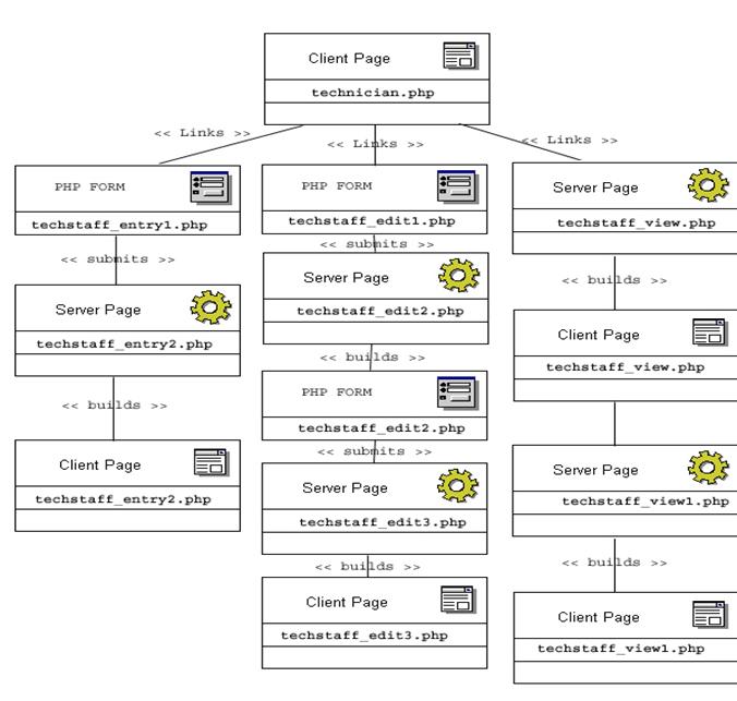
Figure 5.7: web GUI for Technician.
5.5 Summary
This chapter explains the
architecture of a web application, the prototype system architecture and
finally samples of the modeling extension for the web-based graphical user
interface design of the prototype system.