|
EXPERT
TRACKING AND MAINTENANCE SYSTEM
|
THE DEVELOPMENT METHODOLOGY
This chapter briefly discusses the approach
used in Expert Tracking Maintenance System for medium sized organizations. It
covers the Unified Approach (UA) methodology and a brief description of a
Unified Modeling Language (UML).
The
Unified Approach (UA) is a methodology for software development that is
proposed by the author Ali Bahrami (1999). The UA,
based on methodologies by Booch, Rumbaugh,
and Jacobson, tries to combine the best practices, processed, and guidelines
along with the Object Management Group’s unified modeling language. The unified
modeling language (UML) is a set of notations and conventions used to describe
and model an application. However, the UML does not specify a methodology or
what steps to follow to develop an application; that would be the task of the
UA. The heart of the UA is Jacobson’s use case. The use case represents a
typical interaction between a user and a computer system to capture the users’
goals and needs. In its simplest usage, you capture a use case by talking to
typical users and discussing the various ways they might want to use the
system. The use cases are entered into all other activities of the UA.
The UA
establishes a unifying and unitary framework around their works by utilizing
the UML to describe the model and document the software development process.
The idea behind the UA is not to introduce yet another methodology. The main
motivation here is to combine the best practices, processes, methodologies, and
guidelines along with UML notations and diagrams for better understanding of object-oriented
concepts and system development.

Figure 3.1: The processes and components of the unified approach Source: Ali Bahrami (1999).
The unified approach to software
development revolves around (but is not limited to) to the following processes
and concepts. The processes are:
1. Use-case driven development
2. Object-oriented analysis
3. Object-oriented design
4. Incremental development and prototyping
5. Continuous testing
The UA allows iterative
development by allowing you to go back and forth between the design and the
modeling or analysis phases. It makes backtracking very easy and departs from
the linear waterfall process, which allows no form of back tracking.
i.
Object-Oriented
Analysis
Analysis is
the process of extracting the needs of a system and what the system must do to
satisfy the users’ requirements. The goal of object-oriented analysis is to
first understand the domain of the problem and the system’s responsibilities by
understanding how the users use or will use the system. It concentrates on
describing what the system does rather than how it does it. Separating the
behavior of a system from the way it is implemented require viewing the system
from the user’s perspective rather than that of the machine. OOA process
consists of the following steps:
1. Identify the Actors.
2. Develop a simple business process
model using UML Activity diagram.
3. Develop the Use Case.
4. Develop interaction diagrams.
5. Identify classes.
ii.
Object-Oriented Design
Booch, provides the most comprehensive
object-oriented design method. Ironically, since it is so comprehensive, the
method can be somewhat imposing to learn and especially tricky to figure out
where to start. Rumbaugh et al.‘s
and Jacobson et al.’s high-level models provide good avenues for getting
started. UA combines these by utilizing Jacobson et al.’s analysis and
interaction diagrams, Booch’s object diagrams, and Rumbaugh
et al.’s domain models. Furthermore, by following Jacobson et al.’s life cycle
model, we can produce designs that are traceable across requirements, analysis,
design, coding, and testing. OOD Process consists of:
1. Designing classes, their attributes,
methods, associations, structures and protocols, apply design axioms.
2. Design the Access Layer
3. Design and prototype User interface
4. User Satisfaction and Usability Tests
based on the Usage/Use Cases
5. Iterated and refine the design
iii.
Iterative
Development and Continuous Testing
You must
iterate and reiterate until, eventually, you are satisfied with the system.
Sine testing often uncovers design weaknesses or at least provides additional
information you will want to use, repeat the entire process, taking what you
have learned and reworking your design or moving on the prototyping and
retesting. Continue this refining cycle through the development process until
you are satisfied with the results. During this iterative process, your
prototypes will be incrementally transformed into the actual application. The UA
encourages the integration of testing plans from day 1 of the project. Usage
scenarios can become test scenarios; therefore, use case will drive the
usability testing. Usability testing is the process in which the functionality
of software is measured.
3.2 Using UML for Object-Oriented
Development
UML is the current notation of choice for most
enterprise application developers. The UML formally incorporates Use Case as a
modeling technique for defining functional system requirements. Jacobson
introduced the technique in his Object-oriented Software Engineering approach
(Jacobson et al 1992).
With the industry adoption of the Unified Modeling
Language (UML), developers using object-oriented approaches now have a common,
high-level modeling notation for defining and designing their systems (ARTiSAN Software Tools, 1998). The popularity of UML has caused it to be
promoted as a notation for business modeling, as well as its original purpose
of modeling Object-oriented (OO) systems (
The UA uses UML to describe and model
the analysis and design phases of system development.
3.2.1 Introduction to UML
The Unified Modeling Language (UML) is, as its name
implies, a modeling language and not a method or process. UML is made up of a
very specific notation and the related grammatical rules for constructing
software models. UML in itself does not prescribe or advise on how to use that
notation in a software development process or as part of an object-oriented
design methodology (Spark,
2000). There are varieties of diagrams used in UML. Table 3.1 describes several
diagrams used in UML.
Table
3.1: Several diagrams in UML
|
UML Diagram |
Description |
|
Use Case Diagram |
Displays the
relationship among actors and use cases. |
|
Class Diagram |
Models class structures
and content using design elements such as classes, packages, and objects. It
also displays relationships such as containment, inheritance, associations,
and others. |
|
State Diagram |
Displays the entire
sequence of states that an object undergoes in response to received stimuli,
together with the object's responses and actions |
|
Sequence Diagram |
Displays the time
sequence of the objects participating in the interaction. This consists of
the vertical dimension (time) and horizontal dimension (different objects). |
|
Collaboration Diagram |
Displays an interaction
organized around the objects and their links to one another. Numbers are used
to show the sequence of messages. |
|
Activity Diagram |
Displays a special
state diagram where most of the states are action states and most of the
transitions are triggered by completion of the actions in the source states.
This diagram focuses on flows driven by internal processing. |
|
Component Diagram |
Displays the high-level
packaged structure of the code itself. Dependencies among components are
shown, including source code components, binary code components, and
executable components. |
|
Package Diagram |
Shows how classes can
be divided into modules. It also displays the high-level relationships
between packages, of the system, or a specific subsection. |
|
Deployment Diagram |
Displays the
configuration of run-time processing elements and the software components,
processes, and objects that reside within them. |
UML
provides us with a very simple approach to modeling the system requirements.
There are two primary views of the problem that help the developers analyze and
organize a clear definition of the basic functionality of the system. Through
Use Case Diagrams and Sequence Diagrams we can easily model most of the system
requirements. The result of these two graphical views is a rather complete
specification of the system functions,
a general description of the processing involved in each function, a first cut
at the objects involved in providing the functionality, and a general scheme for
the communication between the objects. . (ARTiSAN
Software Tools, 1998)
UML diagrams, which are often
proposed for business process modeling, are the Use Case Diagram and the
Activity Diagram. A Use Case Diagram shows processes in a non-sequential representation,
while Activity Diagrams show sequence in a manner similar to a flowchart. The
UML allows the Activity Diagram to be used to depict procedural flow of control
in several contexts, from Classes and Operation implementations to Use Case (
3.2.2 Use Case Diagrams
Ivar Jacobson developed the use-case
model. The use-case focuses on the requirements of a system rather then the way
a system will actually be designed (Williams, 1997). This makes it a valuable
tool when communicating with non-programmers such as customers and marketing
executives (Douglass, 1997).
In the UML, Use Cases are the primary
means of capturing system functionality from the user perspective, and often
may replace a 'functional requirements' document (Larman,
2001).
A Use
Case represents an interaction between an actor (human or machine) and the
system in performing meaningful work.
Example of meaningful work is login to system, register with system and
create order. Each Use Case has a description, which describes the functionality
that will be built in the proposed system. A Use Case may 'include' another Use
Case's functionality or 'extend' another Use Case with its own behavior. Figure 3.7 depicts the use case diagram.
Included Use Case will be called every time the basic path is run.
An example may be to list a set of customer orders to choose from before
modifying a selected order - in this case the <list orders> Use Case may
be included every time the <modify order> Use Case is run. One or more
Use Cases may include a Use Case, so it helps to reduce duplication of
functionality by factoring out common behaviour into
Use Cases that are re-used many times. One Use Case may extend the behaviour
of another - typically when exceptional circumstances are encountered. For example,
if before modifying a particular type of customer order, a user must get
approval from some higher authority, then the <get approval> Use Case may
optionally extend the regular <modify order> Use Case.
 Figure 3.2: Example of a use case diagram –
Hotel reservation
Figure 3.2: Example of a use case diagram –
Hotel reservation
3.2.3 Sequence Diagrams
Sequence Diagrams capture the
processing associated with particular Use Case functions. The purpose of
sequence diagrams is to display the interaction between users, screens and
object instances within the system. They provide a sequential map of message
passing between objects over time. Frequently these diagrams are placed under
Use Cases or Components in the model to illustrate a scenario, or common set of
steps followed in response to an event that generates
an outcome. The model includes what initiates activity in the system, what
processing and changes occur internally and what outputs are generated. Often,
the object instances are represented using special stereotyped icons. Icons
exist for boundary objects, controllers and persistent entities. The notation used is typically a
horizontally deployed set of actors and object instances, each having a
vertical lifespan bar. Messages are drawn from one object to another
with an arrow indicating the direction of flow. The example diagram Figure 3.8 below
demonstrates some features of Sequence diagrams. Note the use of stereotyped
icons to display particular objects: for example the user interface (Login Screen)
is displayed with a Boundary stereotype and the User as an Entity stereotype.
These help visually differentiate object roles during analysis.

Figure 3.3:
Example of a sequence diagram
3.2.4 Collaboration Diagram
A collaboration diagram describes interactions among
objects in terms of sequenced messages. Collaboration diagrams represent a
combination of information taken from class, sequence, and use case diagrams
describing both the static structure and dynamic behavior of a system.
3.2.5 Activity Diagrams
Activity diagrams are
used to show how different workflows or processes in a system are constructed,
how they start, the many decision paths that can be
taken from start to finish and where parallel processing may occur during
execution. An Activity diagram generally does not model the exact internal behaviour of a software system (like a sequence diagram
does) but rather it shows the general processes and pathways at a high level.
Often it is used to model business activities (such as Selling Books or Manage
Inventory), and may be at a very high level.
Standard UML notation uses a
rectangle with rounded corners to depict an Activity. Activities may be joined
by process flows or events. In addition, a Decision node can model divergent behaviour based on a condition. Typically a Start and End
node are defined to complete the full Activity representation. Synchronization
points may also be defined to illustrate how processing may be carried out in
parallel, then synchronized at a point before further activity is undertaken.
Example 3.9 below illustrates most of these points – it describes the process
surrounding the acquiring of a beverage from a vending machine. The rounded
rectangles are Activities, the diamonds are Decision points and the horizontal
black bars are synchronization points.
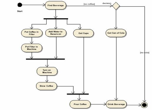 Figure 3.4: Example of an activity diagram
3.2.6 Class Diagrams
A
Class is a standard UML construct used to detail the pattern from which objects
will be produced at run-time. A class is a specification - an object an
instance of a class. Classes may be inherited from other classes (that is they
inherit all the behaviour and state of their parent
and add new functionality of their own), have other classes as attributes,
delegate responsibilities to other classes and implement abstract interfaces.
The
Class Model is at the core of object-oriented development and design - it
expresses both the persistent state of the system and the behaviour
of the system. A class encapsulates state (attributes) and offers services to
manipulate that state (behaviour). Good
object-oriented design limits direct access to class attributes and offers
services, which manipulate attributes on behalf of the caller. This hiding of
data and exposing of services ensures data updates are only done in one place and
according to specific rules - for large systems the maintenance burden of code
which has direct access to data elements in many places is extremely high. The
class is represented as Figure 3.10 below:
Figure 3.5: Example of a class diagram
3.3
The Layered Approach to Software Development
Most systems developed with today’s CASE tools
or client-server application development environments tend to lean toward what
is known as two-layered architecture: interface and data. In a two-layered
system, user interface screens are tied to the data through routines that sit
directly behind the screens; for example, a routine that executes when you click
on a button. With every interface you create, you must re-create the business
logic needed to run the screen. The routines required to access the data must
exist within every screen. Any change to the business logic must be
accomplished in every screen that deals with that portion of the business. This
approach results in objects that are very specialized and cannot be reused
easily in other projects.
A better approach to systems
architecture is one that isolates the functions of the interface from the functions
of the business. This approach also isolates the business from the details of
the data access. Using the three layered approach, you are able to create
objects that represent tangible elements of your business yet are completely
independent of how they are represented to the user (through an interface) or
how they are physically stored (in a database). The three-layered approach
consists of a view or user-interface layer, a business layer, and an access
layer.
3.3.1
The Business Layer
The business layer contains all the
objects that represent the business (both data and behavior). This is where the
real objects such as Order, Customer, Line item, Inventory, and Invoice exist.
Most modern object-oriented analysis and design methodologies are generated
toward identifying these kinds of objects.
The responsibilities of the business
layers are very straightforward: Model the objects of the business and how they
interact to accomplish the business processes. When creating the business
layer, however, it is important to keep in mind a couple of things. These
objects should not be responsible for the following:
Ø Displaying details. Business objects should have no special knowledge of
how they are being displayed and by whom. They are designed to be independent
of any particular interface, so the details of how to display an object should
exist in the interface (view) layer of the object displaying it.
Ø Data access details. Business objects also should have no
special knowledge of “where they come from”. It does not matter to the business
model whether the data are stored and retrieved via SQL or file I/O. The
business objects need to know only to whom to talk about being stored or
retrieved. The business objects are modeled during the object-oriented analysis.
A business model captures the static
and dynamic relationships among a collection of business objects. Static
relationships include object associations and aggregation. For example, a
customer could have more than one account or an order could be aggregated from
one or more line items. Dynamic relationships show how the business objects
interact to perform tasks. For example, an order interacts with inventory to
determine product availability. An individual business object can appear in
different business models. Business models also incorporate control objects
that direct their processes. The business objects are identified during the
object-oriented analysis. Use cases can provide a wonderful tool to capture
business objects.
3.3.2 The User Interface (View) Layer
The user interface layer consists of
objects with which the user interacts as well as the objects needed to manage
or control the interface. The user interface layer is also called the view
layer.
This layer typically is responsible
for two major aspects of the applications:
Ø Responding to user interaction. The user interface layer objects must
be designed to translate actions by the user, such as clicking on a button or
selecting from a menu, into an appropriate response. That response may be to
open or close another interface or to send message down into the business layer
to start some business process; remember, the business
logic does not exist here, just the knowledge of which message to send to which
business object.
Ø
Displaying business objects. This layer must paint the best possible picture of the
business objects for the user. In one interface, this may mean entry fields and
list boxes to display an order and its items. In another, it may be a graph of
the total price of a customer’s orders.
The user interface layer’s objects are identified during the
object-oriented design phase. However, the requirement for a user interface or
how a user will use the system is the responsibility of object-oriented
analysis. Use cases can provide a very useful tool for understanding user
interface requirements.
3.3.3 The Access Layer
The
access layer contains objects that know how to communicate with the place where
the data actually reside, whether it be a relational
database, mainframe, Internet, or file. Regardless of where the data actually
reside, the access layer has two major responsibilities:
Ø Translate request. The access layer must be able to translate any
data-related requests from the business layer into the appropriate protocol for
the data access. (For example, if Customer number 55552 needs to be retrieved,
the access layer must be able to create the correct SQL statement and execute
it.
Ø Translate results. The access layer also must be able
to translate the data retrieved back into the appropriate business objects and
pass those objects back up into the business layer.
3.4
Summary
Unified Approach methodology have five
important phases, which are the Use-case
driven development, Object-oriented Analysis, Object-oriented Design, Incremental
development and Prototyping, and Continuous Testing. Diagrams are used to
represent as much of the data model as possible. The Unified
Modeling Language (UML) is a language for specifying, constructing, visualizing,
and documenting the artifacts of a software-intensive system. The UML has helped a great number of
organizations to manage complexity by providing a common language for creating
and communicating the design of complex software systems. Organizations that
utilize the UML spend less time describing problems and more time building
and implementing robust software solutions.